Correcting the Signal Intensity of Phased Array Coils
The signal intensities of different coil elements of a phased array coil naturally differ even when all coil elements are loaded with comparable samples. As a consequence, the image intensity can show visible variation across a homogeneous sample. These hardware based intensity variations can be corrected by the calibration procedure described below.
The calibration factor is called »Array Element Sensitivity« and is saved in the corresponding coil configuration of ParaVision. The Array Element Sensitivity is then automatically applied for every image reconstruction.
Please note, that the Array Element Sensitivities are not applied on the time-domain data or on the time-domain display.
Step 1: Acquire and analyze the calibration data.
Acquire a set of spin-echo images (MSME method) with a good resolution and good SNR on the specified QA phantom of the coil. The slice positions should be selected such that all coils see comparable portions/distances from the sample and can be single or multi sliced. In general, the correct slice positions for coil calibrations correspond to the slice positions measured for Quality Assurance see coil specific manual.
- ➢
- Reconstruct an uncombined (unshuffled) image and use the ROI tool to analyze the image intensities. Therefore, proceed as follows:
- 1.
- Define a small circular ROI signal and locate it for every coil element on the corresponding uncombined (unshuffled) image such that the ROI is at an identical distance to the coil element.
- ⇨
- To visualize the coil element position, window the images at a high contrast and use the same window scaling for each unshuffled image. Typically, in each image, a brightest area can be identified representing the location of the corresponding coil element.
- 2.
- Define a large noise ROI in a pure noise region that provides the noise as standard deviation within the noise region.
- 3.
- Identify the coil element with the lowest (minimum) signal intensity, i.e. channel iMin
- 4.
- Calculate the signal ratio and the noise ratio for every coil element according to the following equations:
- ⇨
- Signal factor (channel i) = signal intensity (channel iMin) / signal intensity (channel i)
- ⇨
- Noise factor (channel i) = noise (channel iMin) / noise (channel i)
In an ideal case, signal and noise factors are comparable. Sometimes, image artifacts can lead to enhanced maximum signal intensities, i.e. around air bubbles. Bruker therefore suggest using the ratio of the noise factors to set the channel specific image intensity correction factors.
The calibration of the coil elements results typically in more homogeneous image intensity distributions. But this always bears the risk of wrong calibration or a resulting reduction of the signal-to-noise performance of the coil. Reset the calibration (set factor 1 for each element) or repeat the calibration in case images appear inhomogeneous caused by different protocols and setup.
Step 2: Save the correction factors in the coil configuration file.
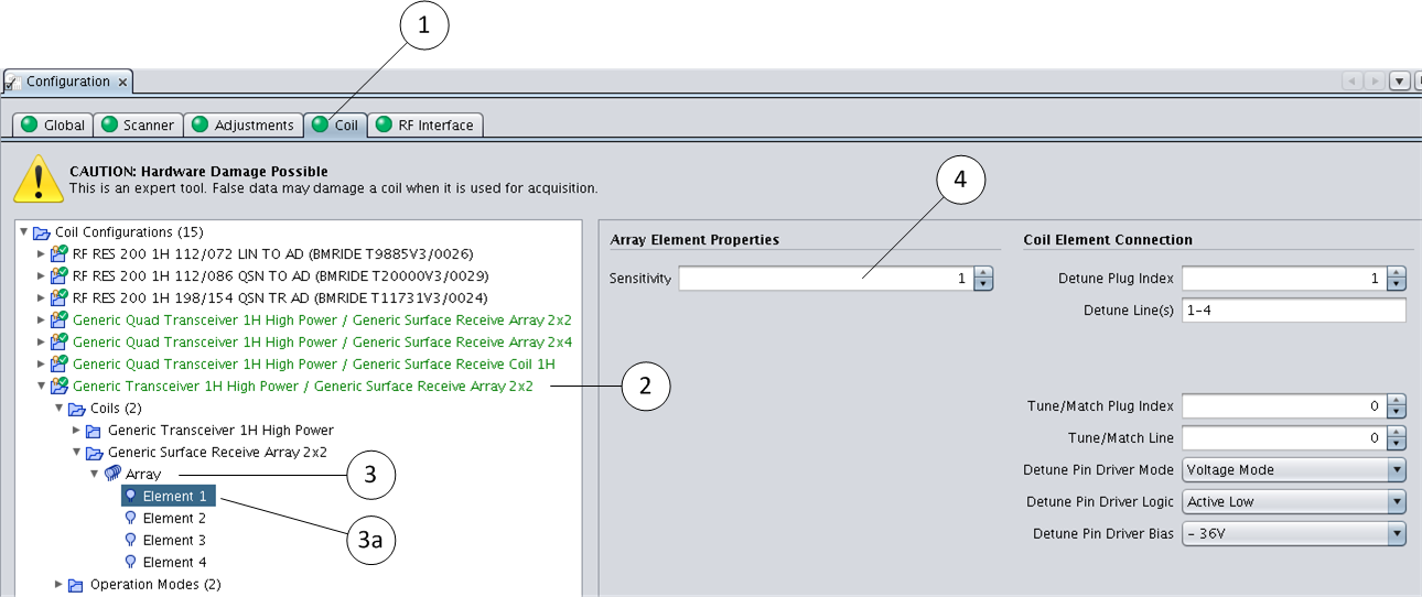
If all factors have been determined, the correction factors are saved. Therefore, proceed as follows:
- 1.
- Open the ParaVision Configuration card
- 2.
- Select and open the coil tab (1)
- 3.
- Select the RF Coil from the list (2)
- 4.
- Expand the categories Coils -> <your array coil> -> Array (3)
- 5.
- Open the category Element 1 (3a) and enter the correction factor for this element into the “Sensitivity” field (4). Repeat this procedure for all array elements.
- 6.
- Select the main category of the modified coil configuration and press the right mouse button to obtain a context menu.
- 7.
- Save the configuration and exit the configuration card.
ParaVision Configuration card


