Animal Body Temperature Conditioning "Air"
Prerequisites
- ▪
- Body Temperature Conditioning System “Water” (option) installed.
- ▪
- Air Supply & Gas Removal Pump (option) installed.
Functionality and recommended settings
The warm water based Body Temperature Conditioning System creates the warm water which is routed via hoses to the instrument and circulates in the Animal Cell Extension (ACE) located just prior to the connector for the animal cradle. In the ACE, there is a water/air heat exchanger.
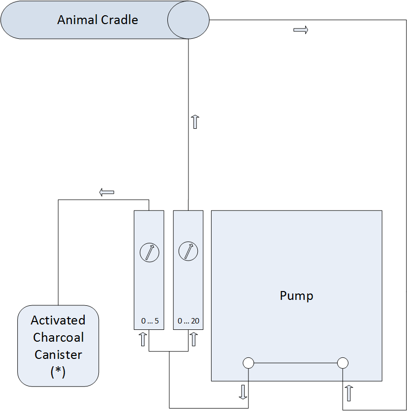
Air flow can be created by the Air Supply & Gas Removal Pump (option, see sketch below) connected to the instrument interface hoses. This air will be warmed in the heat exchanger, transferred into the cradle and therein distributed into three diffusor hoses with small air exit holes in it.
A water bath temperature of about 60 deg. Celsius in combination with an air flow of about 8 to 10 liter/minute (lpm) is recommended which results typically in a temperature required for animal temperature stabilization.
Tip: More air flow will transport more heat and will be more efficient than increasing the water bath temperature.
Air suction is located in the rear of the animal cassette (see cradle interface description) and routed back to the Air Supply & Gas Removal Pump (see sketch below).
As seen in the sketch below, a portion of the circulating air enriched with Waste Anesthetic Gas (WAG) can be passed to an isoflurane adsorber. About 3 lpm is a typical value.
You can regulate WAG and air flow with the two different valves.
In case you need more air flow than the pump can create, you can connect instead of the pump compressed air with a regulation valve to create the air flow to the instrument (e.g. up to 15 lpm, not much higher recommended) . In this case close the circulation flow meter entirely and open completely the meter to the isoflurane adsorber so that maximum air flow is extracted from the cradle. You might even swap the outlets of the two flow meters to allow not only 5 lpm to the adsorber but the maximum number through the 0 … 20 lpm flow meter.
Schematics of Air Circulation
Sketch showing the Air Circulation System (Option Air Supply & Gas Removal Pump). It consists of a diaphragm pump, corresponding hoses, adjustable flow valves with meters for both, the closed air flow circuit to the animal chamber and the extraction pathway to an activated charcoal container *.


