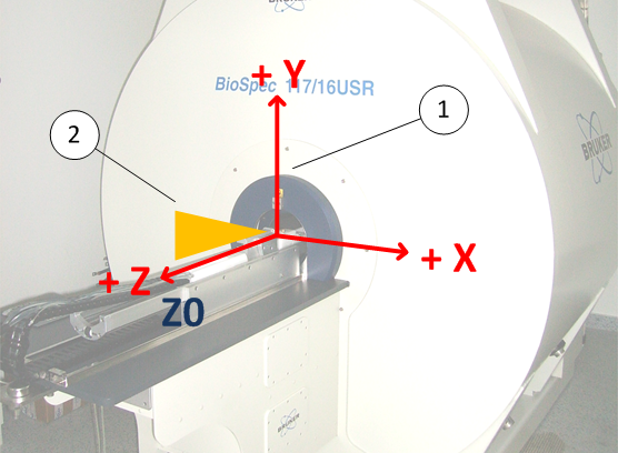
Physical Coordinate System
The physical coordinate system of the MR instrument is defined by the right-handed Cartesian coordinate system as shown in the figure below. This coordinate system is sometimes also called the “magnet coordinate system”. The origin of the physical coordinate system is defined by the magnetic center of the gradient coil. The magnetic center of the gradient coil is aligned with the magnetic center of the magnet1). The magnetic field vector of the magnet is oriented towards the user end and is collinear with the positive field vector of the Z gradient coil2). The shim coordinate system is always defined by the physical coordinate system of the gradient.
Right-handed Cartesian coordinate system
_____________________________
1) Information about distances can be found on the type plate of the gradient and on the type plate of the magnet and are only required when a gradient set is mounted into the magnet. For the magnet, the reference point is the edge of the blue end ring at the service end of the magnet.
2) This is the standard polarization of all Bruker magnets. These magnets have their magnetic south pole at the user end and are sometimes referred to “SN” magnets. The polarization of the magnet is a critical parameter for the imaging coordinate system and for circular polarized RF coils. Suitable circular polarized RF coils are often referred as “QSN” coils.


