Overview
The component cabinet (CCM) is located at the service end of the magnet. The RF coil interface and, in some instrument configurations, also the quick-lock connectors for the gradient exchanging as well as the shim insert are stored in the CCM. In the following figure, the CCM is shown schematically.
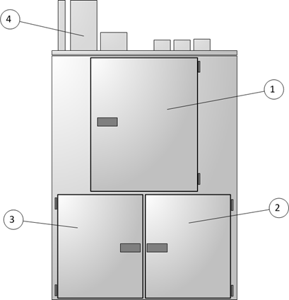
Pos. No | Description |
|---|---|
1 | Central upper door: The central part of the CCM hosts the RF coil sockets to connect RF coils |
2 | Lower right door: The lower right part of the CCM hosts preamplifier, active detuning unit and the automatic hardware recognition units |
3 | Lower left door: The lower left part of the CCM provides all connections points to allow the exchange of gradient and/or shims inserts |
4 | CCM filter panel: Filter and feed through for the external cable set |
The correct function of RF coil configuration depends critical on the wiring between sockets, active detuning module, preamplifier and receiver routing as well as the corresponding interface socket description of ParaVision.
Do not modify neither the configuration settings, nor the DC or RF wiring.
