Principles
Starting the wobble adjustment shows a wobble curve of a selected coil element (see Glossary - Coil Element) inside the Acq/Reco Display. The adjustment normally has to be performed only once per study and uses the protocol Wobble. It can be repeated manually within the Adjustment Platform.
The curve itself represents a measure for the reflected power at the connection point between the spectrometer and an attached RF coil. To guarantee an optimal power transmission at a given frequency, both their impedances have to be matched. Therefore the coils' resonance circuits are typically equipped with two mechanically (or in some cases voltage (“Varicaps”)) controlled capacitors. Altering their capacitance is called “tuning” and “matching”.
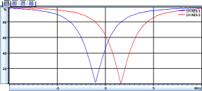
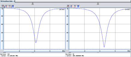
A wobble curve is plotted over a given bandwidth around the nucleus frequency. Single coil elements and simultaneously wobbled elements of array coils are shown inside a single plot, see Wobble curves of a quadrature coil. Simultaneously wobbled elements of multi-resonant coils use one plot each, see Wobble curves of a dual-resonant coil. During wobble the user has to tune and match until the dip reaches the center and its minimum is close to the zero line.
On an instrument equipped with an ATS (Animal Transport System) the wobble curve is also displayed on the touch screen of the HMI/ATS computer (see User Interface of Connected Kiosk Application on Touch Screen While Executing MRI Wobble Adjustment), if the ParaVision instance is connected to the kiosk application on the HMI/ATS computer. Details about using the kiosk application can be found in Chapter Using the Kiosk Application.