How to verify the Image Quality
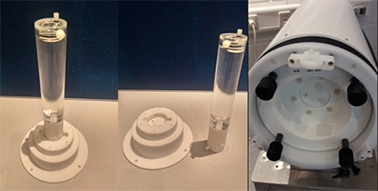
Image Quality performance qualification, is done using the Image Quality Phantoms (IQ Phantoms) filled with FDG and the quality assurance software “Albira Supervisor”.
The following 4 steps are required:
Quality Phantom
Step 1: Phantom preparation and installation
- 1.
- Fill the image quality phantom with 3.7 MBq FDG. Avoid large air bubbles inside the phantom.
- 2.
- Measure the activity of the phantom using a dose calibrator and note the time stamp.
- 3.
- Install the phantom inside the PET Insert. Make sure that the IQ phantom is in the correct position.
Step 2: Acquire the PET data
- 1.
- Use remote desktop to log on the PET RECO Server.
- 2.
- Start the Albira Suite and open the “Acquirer”.
- 3.
- Select the “PET Acquisition Supervisor” template protocol.
- 4.
- Set the Name to “ImageQualityCheck_Date_Activity_Time”.
- 5.
- Select the isotope “FDG” and set the activity and time stamps.
- 6.
- Start the measurement.
Step 3: Reconstruct the PET data
- 1.
- Open the Reconstructor software of the Albira Suite.
- 2.
- Select the dataset “ImageQualityCheck_Date_Activity_Time”.
- 3.
- Select automatic reconstruction.
Step 4: Data Analysis
- 1.
- Open the Supervisor software of the Albira Suite.
- 2.
- Push the “New Quality Control” button.
- 3.
- Select “PET”.
- 4.
- Select the dataset “ImageQualityCheck_Date_Activity_Time” and press START.
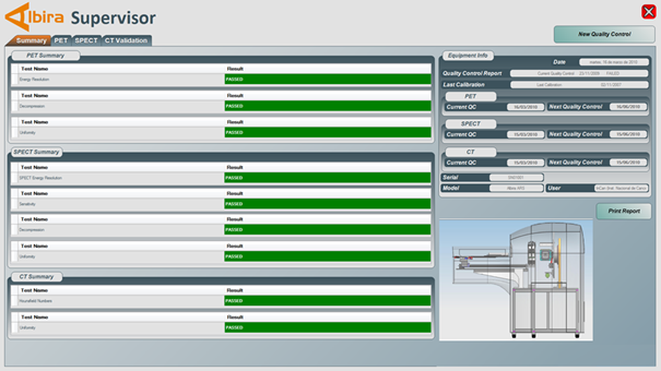
The data analysis will run a few minutes and the results are then presented in the Summary tab of the Supervisor software. Verification tests that have passed the performance criteria are indicated green, failed in red.
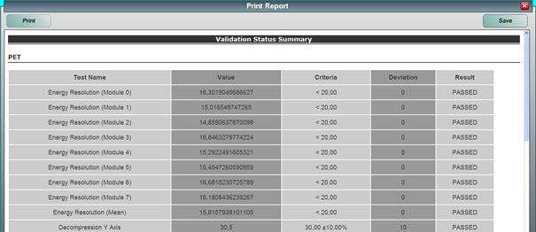
Entering all system information and pressing the “generate a report” will generate a pdf report of the system check that can be stored and used for the longitudinal supervision of the scanner.
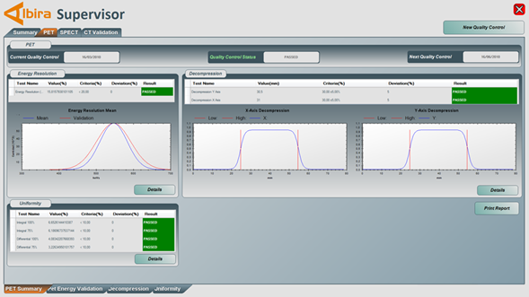
The PET tab of the supervisor provides details of the PET image quality results.
- ▪
- Energy Resolution: The mean energy resolution of each detector is measured and analyzed for all detector modules. The graphs show the mean measured energy resolution in red and the quality control specification in blue.
- ▪
- Geometrical Distortion (Decompression): The size of the sample in the central transaxial plane, as measured from the image width at half height of the phantom is calculated for x and y directions. The deviation from the true width is given in absolute and relative numbers.
- ▪
- Image Uniformity: Integral and differential image uniformities are measured. The 100% value take the entire FOV into account. The 75% value considers only the central 75% of the entire FOV.
- –
- The Integral Uniformity measures the peak-to-peak variation over the specified field of view.
- –
- The differential uniformity measures the maximum variation between any two neighboring pixels within the specified field of view.


